zhec.moe
The Compact Disc Digital Audio System: Modulation and Error-Correction
按:
这篇论文由飞利浦和索尼的工程师共同发表在 1980 年 10 月的第 67 届 AES Convention 上,简明易懂地概述了 CDDA 信号调制方式(EFM)和纠错方式(CIRC)的原理和性能参数,适合希望初步了解这两个子系统的读者。
论文的 PDF 可以在 ResearchGate 下载,我做了 OCR、校对和简单的排版。
本文被 IEC 60908:1999 引用。
The Compact Disc Digital Audio System.
Modulation and Error-Correction.
by
Lodewijk B. Vries, Kees A. Immink, Jaap G. Nijboer, Henk Hoeve
from N.V. Philips, the Netherlands
Toshi T. Doi, Kentaroh Odaka, Hiroshi Ogawa
from Sony Corp., Japan
1. Introduction;
This paper deals with the modulation and error correction of the Compact Disc, digital audio system.
In earlier papers the importance of both issues has already been emphasized: Refs: (1), (2) and (3).
Intensive technical discussions between N.V. Philips of the Netherlands and Sony Corp. of Japan over the past year have led to the agreement upon a technical standard for a digital audio disc, that satisfies the following requirements:
As regards to error correction, the error-correction system CIRC offers:
- High random error correctability
- Long burst error correctability
- A good scratch and fingerprint protection, that means a graceful degradation in case burst correctability is exceeded.
- Simple decoder strategy possible with reasonable sized (external) random access memory.
- Low redundancy not much parity should have to be added
- Possibility for future introduction of 4 audio channels, without changes on the decoder chip.
As regards to modulation, the modulation system EFM offers:
- Low power around frequency zero (almost DC-free)
- High density and simultaneously low sensitivity to optical tolerances.
- Well fitted to error correction
- Self clocking
2. Error-Correcting Block codes: a review of some of its theory.
Before we can explain the CIRC-principle, we have to recapitulate some notions from the theory of block codes.
Error correcting codes can be applied in the situation in which messages have to be sent over (or temporarily stored in) a channel (or medium). In many practical cases one will represent such messages as sequences of symbols. These symbols may in some cases involve a single choice out of two possibilities in which case we then talk about bits, but for other cases it turns out to be more practical to consider small groups of say $s$ consecutive bits as a symbol. In the latter case, there are $2^s$ possible values that a symbol can take.
Since in practice we want to transmit a great number of messages, we group $n$ consecutive symbols together to form words of fixed length. Furthermore we assume that the receiver knows via some technical provision, where the beginning of each word is located. Such a provision is called the synchronization system, in that case we can conclude that a symbol is received incorrectly if and only if the channel made a transmission error.
Coding theory deals with the following situation, suppose we are satisfied with the situation in which, we effectively transmit only $k$ information symbols per transmitted codeword consisting of $n$ symbols, where $k \lt n$, but require that errors to a certain amount in each codeword should be recoverable. The best code in such a situation, is obviously the one, which for fixed values of $n$ and $k$ can correct the largest amount of independent errors. It turns out that if the code is restricted to be linear (which is for large codes an almost necessary requirement for realizability), the best codes one can get if $s \gt 1$, are the Reed Solomon codes, since for those codes it suffices to have only $(n-k)=2t$, to be able to correct for $t$ symbol errors in each word.
Error correcting capabilities of codes are usually discussed at the hand of a certain quantity called minimum distance. The distance $d(x, y)$ between two $n$-symbol words
$$x = x_0, x_1, x_2, \ldots x_{n-1}$$ and
$$y = y_0, y_1, y_2, \ldots y_{n-1}$$
is the number of places $i$, in which $x_i \ne y_i$ for $i = 0,1, \ldots n-1$.
The minimum distance of the code now is defined as the minimum of the distances between all pairs of different codewords, this quantity we will denote by $d$. Thus if $d$ is the minimum distance of the code we are now sure that given a codeword $x$, it will take at least $d$ symbol alterations on $x$, in different positions, to arrive at any other codeword $y$. From the following argumentation it can be understood that a code is $\bm{t}$-error correcting if and only if $\bm{d \ge 2t+1}$.
Suppose the decoder possesses the very large table of all legitimate codewords, if he receives a word $z$ which is the result of at most $t$ symbol alternations in the transmitted codeword $x$, we immediately conclude that the originally transmitted codeword will be found as the unique codeword $x$ for which $d(x, z) \le t$. The important thing to recognize is that all other codewords $y \ne x$, will have $d(y, z) \ge t+1$.
This can be seen as follows, first note that it takes at least $(2t+1)$ symbol alterations on $x$ to reach $y$, worst case $t$ of them might have been done already in producing (the non-codeword) $z$, hence it takes at least $(t+1)$ more symbol alternations on $z$, in order to reach $y$.
This way, a simple (but tedious to exercise) decoding rule is to compare the received word $z$ with the list of all codewords and select the unique code word $x$, for which $d(x, z) \le t$.
Of course this is not a practical decoding algorithm, it delivers however constructive proof of the error correcting capability of the code.
To get a full understanding of the decoding of CIRC, the reader should also be familiar with the concept of an erasure. A position $i$, is called an erasure position if (via some external means, it was decided that) the value of the received symbol $z_i$ of $z$, is doubtful.
If erasure information is available, the decoder knows where some of the errors may be located and this will facilitate the decoding in general.
If with almost certainly all errors can be detected at forehand as erasures, (via some sophisticated external means) the decoder is very good off, as can be concluded from the following assertion.
If a code has minimum distance $\bm{d}$, it can correct (resolve for) $\bm{(d-1)}$ erasures.
Also this result can be proven by showing that there exists a decoding algorithm which will work. Let $x$ be the transmitted codeword, $z$ be the received word, counting at most $(d-1)$ erasures, then obviously $d(x, z) \le (d-1)$.
We now start making symbol alterations on $z$, but restrict those alterations only to the erasure positions. Let $\tilde{z}$ be the result of making at most $\bm{(d-1)}$ symbol alterations on $z$, restricted to the erasure positions, then any such $\tilde{z}$ still satisfies $d(x, \tilde{z}) \le (d-1)$, which implies that $\tilde{z}$ can never result into a code word other that $x$.
By running over the finite set of all allowable alterations on $z$, some $\tilde{z}$ will however be equal to $x$, which terminates the decoding.
The reader should now have become aware of the central importance, the minimum distance of the code has, when it comes to correcting errors and erasures.
3. CIRC : Cross Interleave Reed Solomon Code
CIRC makes use of two Reed Solomon codes, the first one, which we will denote by $C_1$ has $n_1 = 32$, $k_1 = 28$ and $s = 8$, the second one, referred to as $C_2$ has $n_2 = 28$, $k_2= 24$ and $s = 8$.
Since both codes have $n-k=4$, their minimum distances are 5, which may be used for either 2 error correction, 4 erasure correction, or some other combined strategy.
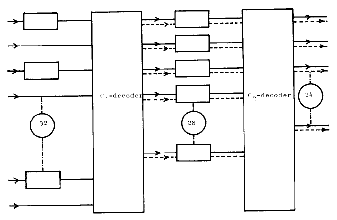
Fig. 1 CIRC decoder principle;
The decoder principle will now be discussed at the hand of fig. 1, where the 2 decoders are referred to as $C_1$-decoder and $C_2$-decoder. The horizontally laid down rectangles represent (8bit-wide) symbol delay lines, implemented as shift registers. Those delay lines connecting the output of the $C_1$ decoder with the input of the $C_2$ decoder are of unequal length, that is their delay in terms of symbols is different. All delay lines connected with the input of the $C_1$ decoder have one and the same length. Input to the decoder is a frame, which is a word of 32 symbols long, transmitted in serial manner.
The sequence of frames forms a cross-interleave code, which means that, with this configuration of delay lines, both the $C_1$ and $C_2$ decoder, will receive code words according to the encoding rules for $C_1$ and $C_2$ respectively, when no error in the transmission of frames occurs.
In this set up, the $C_1$ decoder works as a single error correcting, not a double error correcting device.
The reason for not making use of the full correcting capability of the code is, that its detecting capability for uncorrectable errors gets very high. If more than one symbol is in error, then regardless of the number of errors, the probability that this word shall not be detected by the decoder as being uncorrectable is accurately approximated by:
$$P_{\text{undet}} \approx \frac{1 + n_1 2^s}{2^{s(n_1 - k_1)}} \approx 2^{-19} \approx 1.91 \times 10^{-6}$$
(except for 2 and 3 errors which will definitely be detected.)
Thus with almost certainty if the $C_1$ decoder receives a burst containing many errors, it still can detect the event of an uncorrectable word. When this is the case it lets pass through 28 symbols uncorrected (solid lines), but an erasure flag is given out on all these symbols (dashed lines), to mark that all symbols given out at that moment are unreliable.
Now because, the delay lines between the $C_1$ and $C_2$ decoder are of unequal length, the symbols that received an erasure flag at one instant, will now arrive at different instants at the $\bm{C_2}$-decoder input. Thus the $C_2$-decoder has for every symbol an indication whether it is an erasure or not. Practically speaking if a symbol does not carry an erasure flag it is error free. If not more than 4 symbols carry an erasure flag, the $C_2$-decoder can do a correction. In case even the $C_2$-decoder cannot correct, it lets pass through 24 data symbols (equivalent of 12 audio samples) uncorrected, but marked only with those erasure flags originally given out by the $C_1$-decoder.
This way even if the $C_2$-decoder cannot decode, still most of the symbols are probably error free, and the erroneously marked sample values can be reconstructed via linear interpolation.
4. Specifications of C.I.R.C.
In specifying the performance of a coding system for disc applications both the burst error correcting and the random error correcting capability as well are important.
The first one is specified in terms of the maximum fully correctable burst length and the maximum concealment length, the latter being the maximum burst length for which all uncorrected samples out of the decoder, can be reconstructed via linear interpolation among adjacent samples. The random error correcting capability is specified in terms of the number of audio samples that will have to be reconstructed via interpolation, (the so-called sample interpolation rate) given a random bit error rate B.E.R. on the channel. The following table lists the most relevant specs of the CIRC-system:
| Aspect | Specification |
|---|---|
| max. fully correctable burst length | up to 4000 bits (2.5 mm) |
| sample interpolation rate | 1 sample/10hrs at $\text{BER}=10^{-4}$ 1000 samples/min. at $\text{BER}=10^{-3}$ (which is 1 out of 2.6 million on the average). |
| undetected erroneous samples (clicks) | less than 1/750hrs at $\text{BER}=10^{-3}$ negligible at $\text{BER}=10^{-4}$ |
| code-rate (efficiency) | 3 data bits will result into 4 bits after encoding, on the average. |
| decoder-complexity | 1 special purpose LSI + 1 2K words of 8 bits RAM |
| compatibility with future 4 channel versions | No changes in the decoder-chip required. |
5. The modulation system
The NRZ-signals from the A/D-convertor and the error correction parity generator may have a high dc-content and are not self-clocking (the run-length* is not limited). Therefore they cannot be used on the disc.
The signals have to be converted into another code which should meet some special requirements.
* Run-length = distance between transients in the signal.
5.1 Requirements for the modulation system
a. Clock-content
The bit-clock must be regenerated from the signal after read-out. Therefore, the signal must have a sufficient number of transients and the maximum run-length (Tmax) must be as small as possible.
b. Correct read-out at high information densities.
The light-spot with which the disc is to be read out has finite dimensions. These dimensions give rise to intersymbol-interference. This effect can be minimized by making the minimum run-length (Tmin) as large as possible. So a good technical compromise between Tmin and clock content has been made on experiments.
c. Servo
The modulation code must be dc-free, because the low-frequencies of the spectrum give rise to noise in the servo-systems.
d. Error-propagation
The error-propagation of the modulation system should be limited to the eight consecutive data bits forming a symbol.
5.2 The Eight-to-Fourteen modulation (EFM) code.
- Each block of 8 data bits is mapped into 14 channel bits. To each block of 14 channel bits 3 extra bits are added, for merging and for low freq. suppression.
- The information is contained in the positions of the transients. For mapping 8 data bits 256 combinations of channel bits are needed.
- The code is constructed in such a way that the minimum distance between 2 transients is 3 channel bits (≈1.5 data bits) and the sampling window or eye-pattern is 1 channel bit (≈0.5 data bit).
This yields a good compromise between intersymbol-interference and clock accuracy (phase-jitter). The maximum run-length within the blocks is 11 channel bit (5.5 data bits)
(see fig. 2) - Since the extra 3 bits do not contain any information, an extra transient may be inserted in these bits. In this way the maximum-run-length (Tmax) between two blocks and the dc-content of the frequency spectrum can be controlled.
- The modulator and demodulator can be realised with a look-up table in a ROM.
- Because of the block structure this modulation code is extremely suitable for use in conjunction with the error-correction system, which operation is also based on 8-bit blocks.
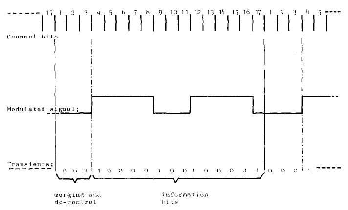
Fig. 2 Modulation Example
5.3 Frame format
Because the system must be self-clocking synchronization is necessary. Therefore the data stream is split up into frames.
Each frame contains:
- a special synchronization pattern
- 12 data words of 16 bits each
- 4 error-correction parity words of 16 bits each
- a control & display symbol of 8 bits.
The data and error-correction words are each split up into two 8-bit blocks, which are fed into the modulator circuit. After modulation each block is converted into 3 + 14 channel bits.
The total number of channel bits per frame is:
- sync pattern: 24 channel bits
- control & display: 1 x 14 channel bits
- data: 12 x 2 x 14 channel bits
- error correction: 4 x 2 x 14 channel bits
- merging and LF suppression: 34 x 3 channel bits
Total: 588 channel bits
References:
(1) T.T. Doi; "A Long Play Digital Audio Disc System", presented at the 62nd AES Convention, AES preprint nr 1442 (G-4)
(2) G. Fukuda and T.T. Doi; "On Dropout Compensation of PCM Systems-Computer Simulation Method and a New Error-Correcting-Code (Cross Word Code)", presented at the 60-th AES Convention, AES preprint nr 1354 (E-7)
(3) L.B. Vries; "The Error Control System of Philips Compact Disc", presented at the 64-th AES Convention, AES preprint nr 1548 (G-8)